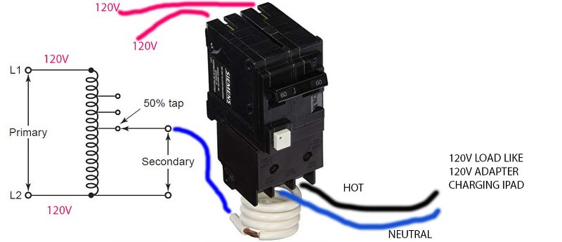
I setup the above to make a temporary gfci tester or tripper. The white button works manually, but when I plugged in a load to the hot and neutral output of the gfci 2-pole breaker, why didn't it trip it? I understand the GFCI monitors the current between the 2 hots, so when there is a leakage, it trips.
Why can't the hot to neutral output be considered a leakage?
Original message:
I have searched the archive, but couldn't find question or answer to this supposedly common question.
I have successfully connected 2 US Siemens 2-pole GFCI breaker and the outlet has 240v. Can I use the ordinary 120v GFCI tester for this 240v outlet? Is the circuit inside the tester only for 120v and what would fry if the source is 240v?
I can't use the European RCD tester because their test leakage current is high 30mA. US GFCI tester has 5mA trip rating and test signal.
If no product can be found for this. Any way to test if the 2-pole gfci breaker is working (besides testing its self test button)? I want to test the outlets connected to it 1 floor away of leaking 5mA can trip the gfci breaker.
Best Answer
No. A standard US 120V GFCI tester has a NEMA 5-15 plug. It is physically unable to plug in to a 240V circuit.
Receptacles used on 240V circuits are keyed differently, precisely to keep that kind of mistake from happening. Obviously it is a mistake because it would wreck any equipment plugged into it (including, possibly, a GFCI tester). Even if it happens to inconvenience you right now.
Anyone using a NEMA 5 on any voltage other than 100-132V should not be playing with electricity. They should use Euro style plugs, unless they have the unique center ground of some parts of the Philippines, in which case NEMA 6 would be just right... but given Philippine ambitions, I would think they'd be standardizing the country on one of the Euro plugs.
Someone who should be playing with electricity may note that the GFCI tester is simply a resistor that allows a calibrated amount of current between hot and ground, inducing a ground fault just above detection level. Now if you were doing this in Europe, or Euro-wired sections of the Philippines with 240V between hot and ground, the Resistor would be seeing 240V instead of 120V, and flowing twice the current, possibly to its destruction.
However, if you are in a US-legacy section of the Philippines where ground is centered between the two hots, then the resistor is of the correct value. One could use a custom cheater cord to use the GFCI tester as intended. However, that would only test one "hot". To test the other hot, one would need a second cheater cord with the second one cross-wired. These cheater cords would be harmless; you wouldn't connect the cheater's NEMA 5 socket neutral to anything at all, and only connect one of the plug hots, so if someone accidentally connected a 120V appliance it would not power up.
If your socket is flippable Euro style, then you wouldn't need 2 cheater cords, you could just flip the cheater cord over.
What you just drew in your recent edit, is not a ground fault. It is the GFCI working as intended. Currents through the GFCI device on L1 and neutral will cancel out, with nothing on L2, so currents sum to zero and no trip. Note that the GFCI is not comparing currents on the two wires you want it to. It is comparing currents on all three. If they add up to zero (all current going out comes back), no trip.
The GFCI tester trips because its current is coming out L1, which does go through the GFCI, and going back on ground, which does not go through the GFCI. Hence it does not see the return current, and sees currents as not adding up to zero, and correctly trips.
Do not ask more than 25 watts out of either side of that transformer, or you will overload it. One iPad is fine. Two would be at transformer limits.