TOTALLY DIFFERENT ANSWER FROM THE ORIGINAL:
The original answer was not complete and had some misunderstandings. I hope to clarify here.
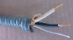
First off, there are many types of armored cable, most of which are colloquially called "BX". By "older BX" I assume you mean something like the wire at the bottom of this image:

Two conductors, no ground wire, no bonding strip. This kind of wire is an older design predating the grounding requirement. If the wire is original to the house, it was not designed to have the armor grounded (because it's 20 years older than the NEC grounding requirement itself). It's still available (hence the newer PVC insulation and overall new condition of the wire in the picture) because there are still situations in which it can be used safely (and jurisdictions that don't care); however, your situation and location probably falls under neither of those.
It can be dangerous to use the armor of older, "non-bonded" BX cable as a ground connection because:
- The armor of this older cable was never rated to transmit current, much less 15+ amps of it; if it is too thin, or the run too long, it can present high resistance to current along its length, meaning less current will flow through it in a failure situation, and so the breaker may not trip when it is supposed to.
- The armor may be aluminum (in fact it is likely to be), which is highly "anodic"; where aluminum touches copper (such as your proposed join between the copper Romex ground and the armor), or iron/steel (nails/screws/pipes), or really any metal besides other aluminum, zinc or magnesium, the aluminum will corrode preferentially when given any excuse at all (humidity, salt, high temperature, electrical flux) and eventually your ground path will fail.
- Continuity of the armor becomes a primary concern; if the armor is damaged, its continuity can be reduced or destroyed. This can be problematic when the primary purpose of the armor as designed was to take a beating.
- Aluminum, when an electrical current passes through it, heats up more than copper. In a sustained failure situation that doesn't pop a breaker/fuse, this could end up being a fire hazard, especially if there is increased resistance due to damage at any point in the armor.
It's possible, and it may even be likely, that you'll never have a problem, but electrical codes are extremely pessimistic for a reason. When "possible" takes another job on Murphy's side, and "likely" don't want to come in to work that day, that's the day you have a problem.
Nowadays, type AC cable (modern "BX") looks more like the following:
Notice the bare wire. This type of cable is designed specifically to have its armor and this "bonding strip" form the ground path in combination. You do still have to be careful about what you connect it to:
- The bonding strip may still be aluminum, as in the picture (though copper-bonded AC cable is available); if so, it should not directly touch any copper or steel. You should instead ground the J-box (typically galvanized or zinc-plated steel; the zinc coating in either case protects both the steel and aluminum from galvanic corrosion) through the wiring clamp by bending the bonding strip backwards so it's also held by the clamp, then attach the copper wire somewhere else in the box (there are usually other attachment points in the J-box for just this purpose).
- The bonding strip is 16AWG, because it's designed to complement the armor; if the armor is fully compromised at any point along its length, however, the bonding strip is all that's left, and it's 2AWG smaller (and aluminum provides more resistance) than the minimum gauge of copper wire rated for 15A.
This all just means you should be careful when installing it, to make sure that you don't abuse the armor or create a galvanic cell in your J-box. You also must not install this wire in any location where water could be an issue; instead, you should use a Type MC cable with a PVC outer jacket. However, if installed properly, this type of wire is perfectly safe.
Looking at the first image again, the middle cable is an example of non-bonded, grounded BX, known in the NEC as type MC (though newer MC has an extra PVC jacket between the conductors and armor; it's basically armored Romex). Because it doesn't have a bonding strip, the armor of this cable should not be used as ground. Instead, the green wire (in the image it's a very blue-green) should be used as the ground connection. MC severs these two responsibilities; the armor is there to take abuse, the ground is there to add electrical safety to the circuit.
3-way switches can seem a little bit like magic, I suppose. ;-)
What happens is that power comes into one switch on the "common," travels to the other switch over one of the "travelers," depending on the position of the switch, and then depending on the position of the switch on the far end, power will travel out of that common to the light(s). If the 14-3 or 12-3 wire only runs between the switches (not through the light fixture), then the "common" in that cable will be the hot conductor coming back from the far switch, in which case it should be connected to one of the black wires, which supplies power to the light. But if the red/black/white cable runs through the light fixture, it might be wired up differently.
In your case, it looks like power is probably coming into the box with the multiple "romex" cables entering it. One of the incoming 14-2 or 12-2 cables brings power in, and the other takes power to the light. That means the white wires in those black/white cables are neutrals, while none of the 3 wires connected to the switches are neutrals.
Your occupancy switch requires a neutral connection in order to function.
Best Answer
Since you are on breakers 10 & 12 it is probably a multiwire branch circuit sharing the neutral, today's code requires handle ties if this is the case. Verify the hot feeding the light and switch. A noncontact tester may show a hot line or a phantom induced voltage. Depending on the wiring it could be a switched neutral this would be a code violation and is common in home owners doing there own wiring. The correct way would be to take the black wire that feeds the light and connect it to the black that goes to the switch, in the switch box the white wire that comes in with the black needs to be marked with paint or electrical tape a color other than white or green. The white in the light on the same cable feeding the switch needs to me marked also. Heat lamps usually take special fixtures that have high temp wires and many of the heat lamp fixtures have a maximum wattage of 300w some much less. Excess wattage lamps can be the cause for the discoloration of the insulation. The wiring needs to be evaluated and possibly repaired with proper junction boxes added. It would be a good idea to add handle ties to breaker 10-12 if it is a multiwire branch circuit. They may not have been required when the home was wired but are a good safety feature now. This or replacing the 2 breakers with a double pole breaker with 1 handle.